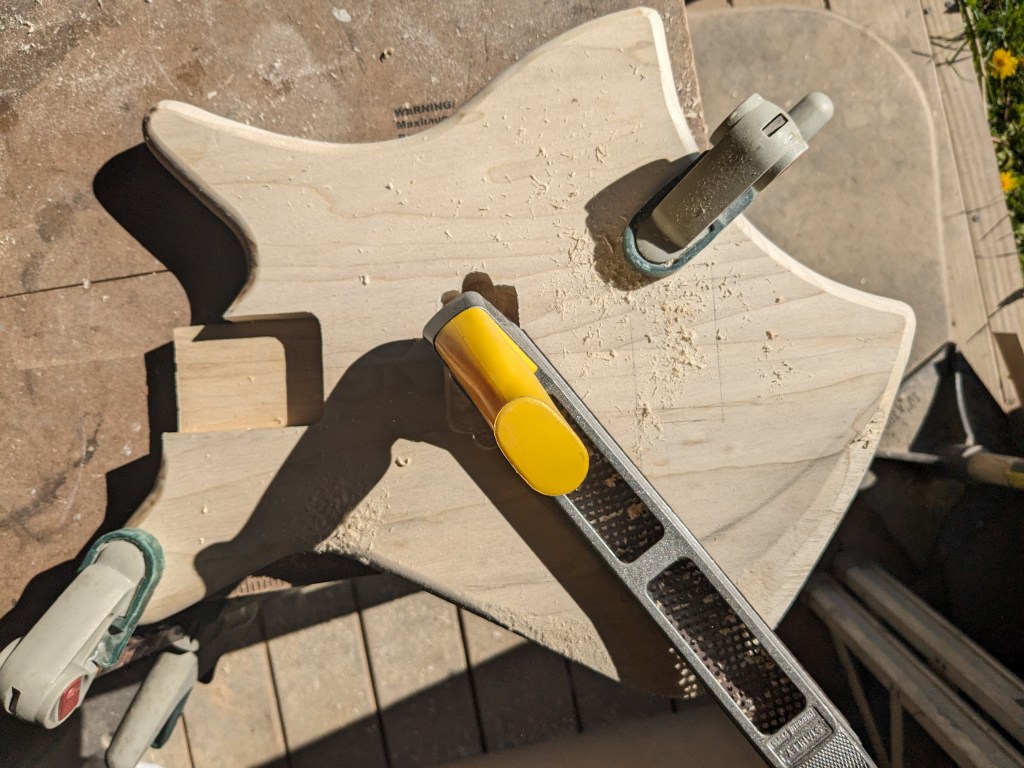
Once I had the body glued up, it was time to shape and sand it. I started by rounding over the edges, then got to work with a rasp to start contouring the arm rest area. This will reduce the weight a little and making it more comfortable to play.
Once I had the contouring done, I drilled for the volume and tone pots, the jack, the bridge (including the grounding wire channel, and the neck screws.
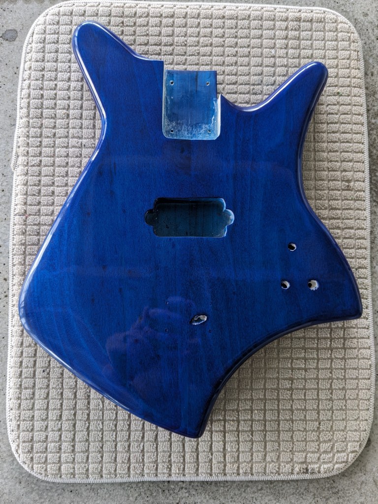
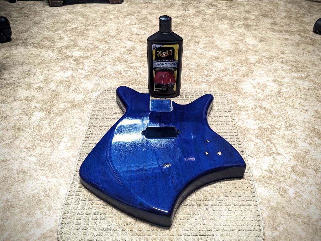
I didn’t take any pictures of the sanding process, but once it was done, it was time to add a little color. I really wanted to blue to stand out on this one so I started by staining the body with ColorTone liquid stain. This alone is usually good enough, but I wanted to enhance this with Metalcast Blue Anodized coating. This is a translucent blue finish meant to go over chrome or bright metal, but it works just as well over wood. I topped this off with Rust-Oleum Triple Thick Glaze. I gave each of these layers ample time to cure between coats, then let the whole stack rest for a week before wet sanding and polishing with Meguiars compound.
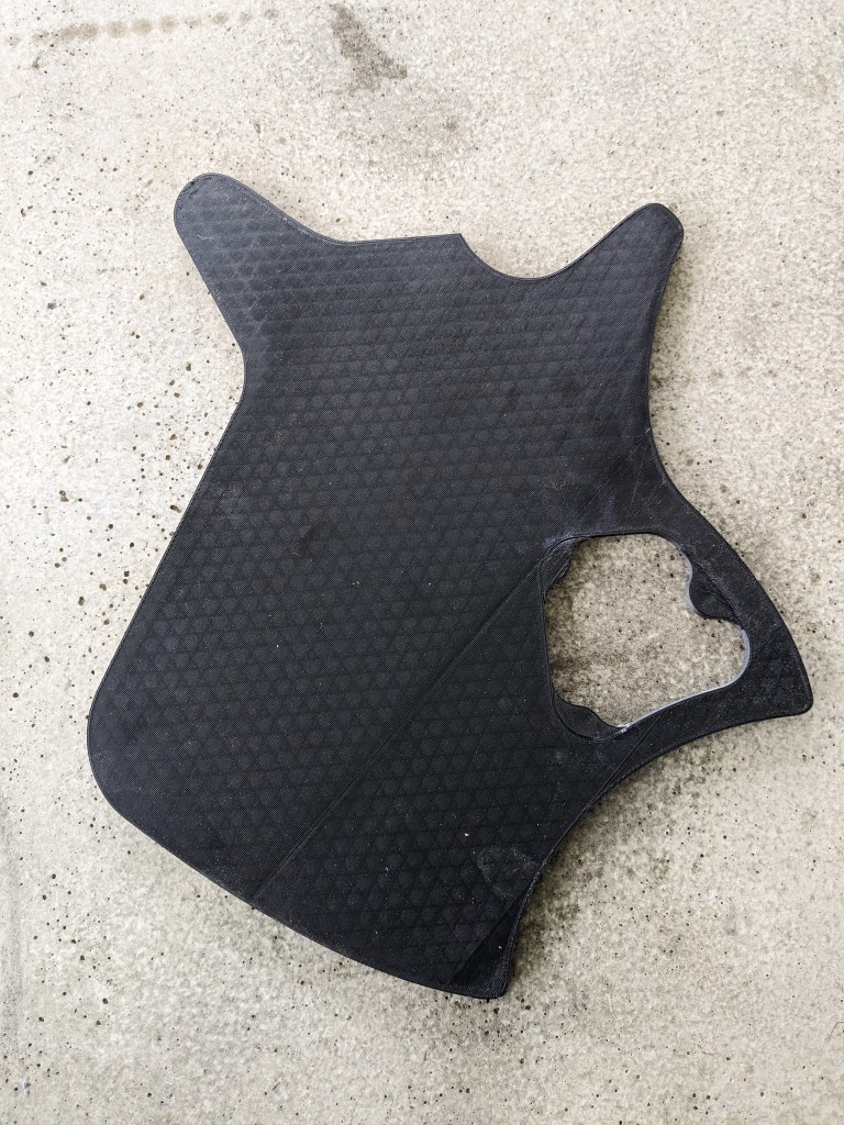
Once I had my design modeled in Fusion 360, I modeled the routing jigs I would need, and started 3D printing them. This included the body templet with the control cavity cutout and the control cavity cover routing templet. These are printed 1/4″ thick, then I use double sided “carpet” tape to adhere them to 1/2″ MDF and route to make a template that is 3/4″ thick. I do this because the 3D printed template is susceptible to heat. Routing the mdf doesn’t produce a lot of heat, but trying to rout 3/4″ or 1.5″ poplar does, and can actually start to deform the 3D printed plastic.
While the templates were printing, I glued up the blanks for the body, which you can see in the second picture. I took a 1″x8″x6′ poplar board and cut it into four 18″ long pieces, then edge glue two pieces together for the top and two pieces together for the bottom. then I planed them . Unfortunately, I didn’t take any pictures of this process.
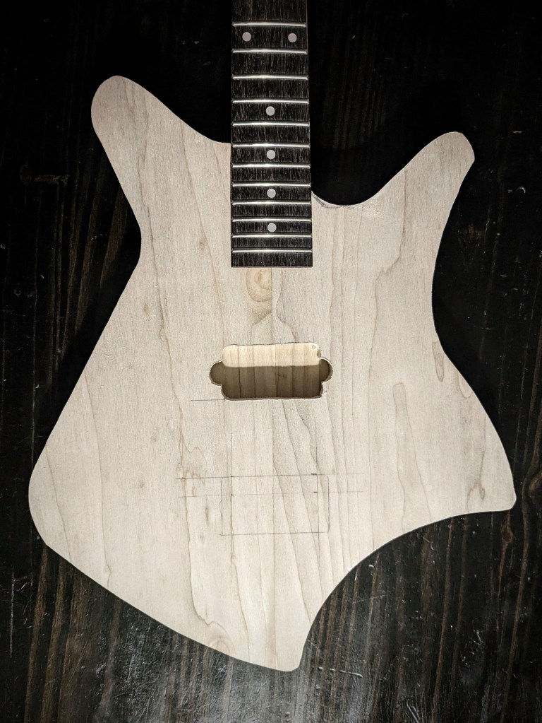
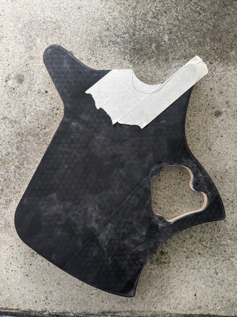
Once the blanks were ready, I traced out the template onto them and used a band saw to cut them almost to size. Then, routed exactly to size. At that point, I couldn’t resist a little mock up with the neck. This allowed me to layout the neck pocket, pickup cavity and bridge placements.
After mocking up the guitar, I realized that the cutout didn’t quite allow enough access to the lower part of the fretboard, so I freehanded a deeper cutout.
With the majority of the cutting and routing done, I glued up the top and bottom halves, using almost every clamp I own:
This is a part I definitely didn’t want to rush, so at this point all I could do was wait.
Once I had the basic 2D design established in Adobe Illustrator, I exported it as an SVG file so I could import it into Autodesk Fusion 360. Even though svg files are vector graphics, there is a discrepancy in how Illustrator and Fusion understand the size based on pixels. Illustrator treats the file as 72 dpi and fusion expects 96 dpi, so when importing an svg from Illustrator to Fusion you have to scale it 72/96% or a factor of ~1.33333.
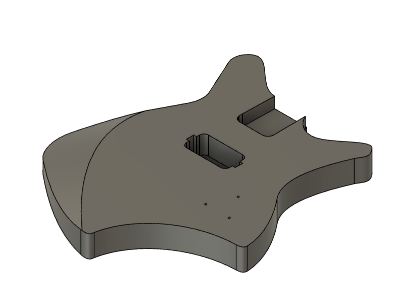
Once imported, I extruded the body, then decided on the control cavity shape, the pickup routing cavity and the neck routing. In designing this guitar, I had a few criteria in mind. I wanted this guitar for playing heavy metal music, which meant I wanted a powerful humbucker pickup. A few years ago I used a BK2000 in a build. This is a quad rail pickup rated at 18 kilohms and has wiring so it can be split, making it even more versatile. I’d even bought an extra one at that time, so it was a no brainer to use it on this build.
Another criteria was the size. I wanted this to be as small as possible while remaining a full size guitar. In other words, I wanted it to be light, and compact to make it as easy and fast as possible to play, which really made me reconsider scale length. Scale length is the distance from the nut (top of the neck where the strings rest) to the bridge (part on the body that holds the strings. Manufacturers have used various scale length over the years, but Fender really standardized the 25.5″ scale length, and this is what I’ve used for all of my six string guitars so far. Lately, though, I’ve found that I really prefer a 24″ scale for my 3-string guitars, so I decided to use it on this design as well. Some manufacturers have sold 24″ scale guitars in the past as “student models”, so I am optimistic that this guitar should be easy to play.
Once I knew what pickup and neck I was going to use, I was able to place the cavities for these:
Next was the control cavity. Even though I was only going to have a push-pull Tone pot, Volume pot and jack, I wanted a large cavity to help reduce weight. I also wanted to to be easy to route, so I designed everything with a half-inch router bit in mind. This is what I came up with:
When I had the design done, I 3d-printed the routing templates and was ready to start the build!
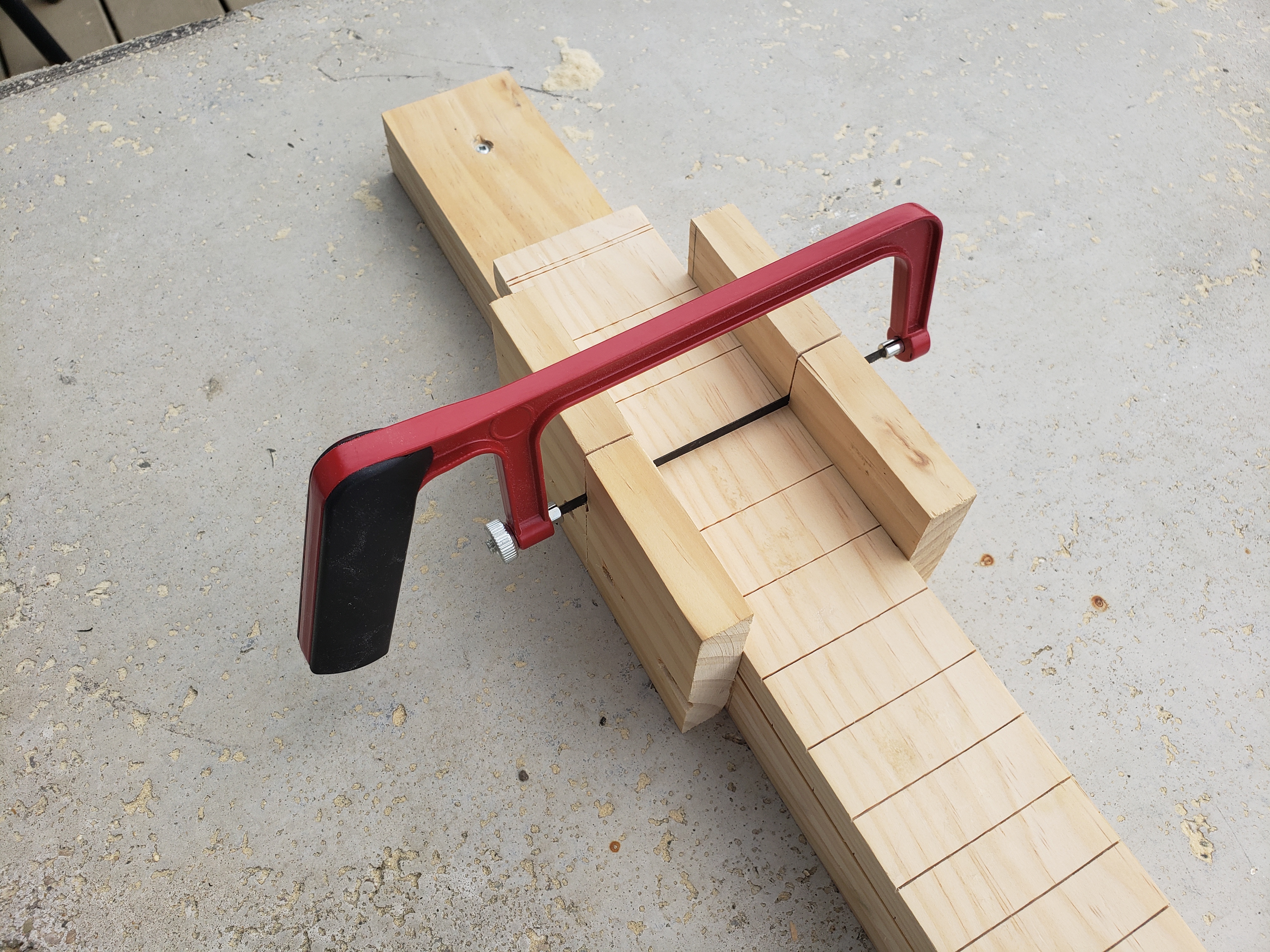
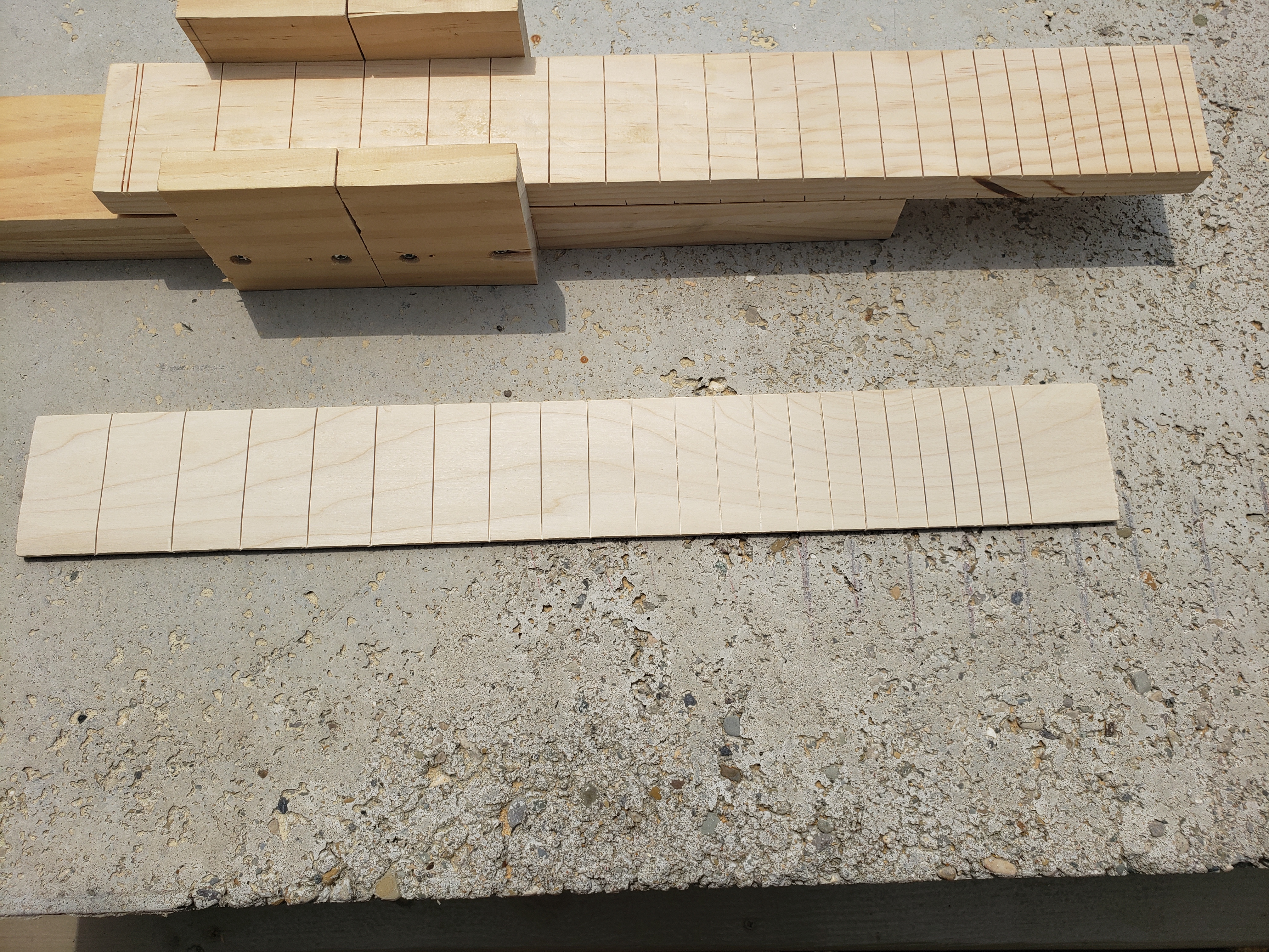
The most critical part of a guitar is the fretboard. To make sure every fret is exactly where it belongs, I created yet another jig. I don’t remember exactly where I first saw this jig online, but there are many sites, books and videos showing how to make this. The jig is basically a very precise miter box.
A lot of people prefer to use expensive fret saws but I don’t have that kind of money to through around on something I’ll only use a couple times a year, so I went with a cheap plastic saw that cost me $8. It seems to cut perfectly straight and the replacement blades are extremely cheap.
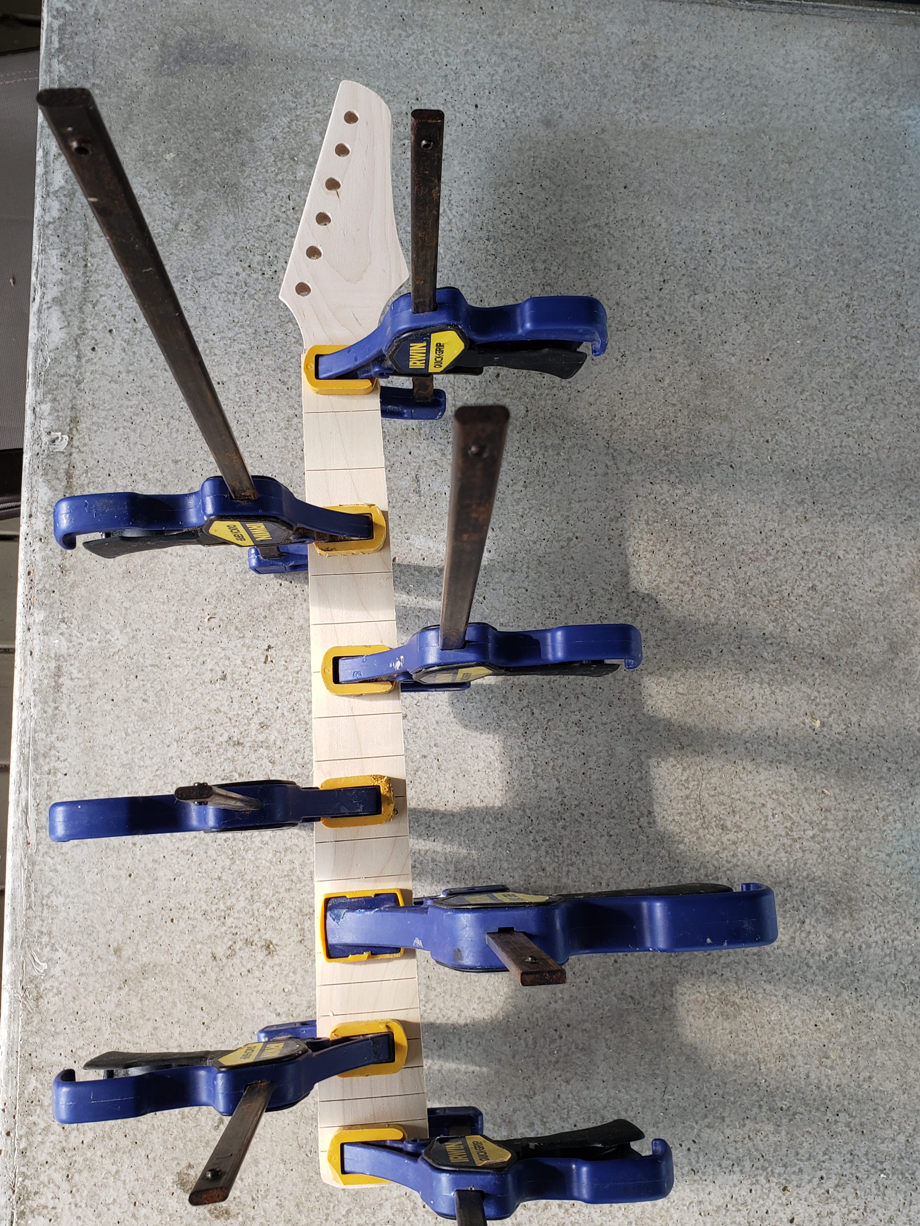
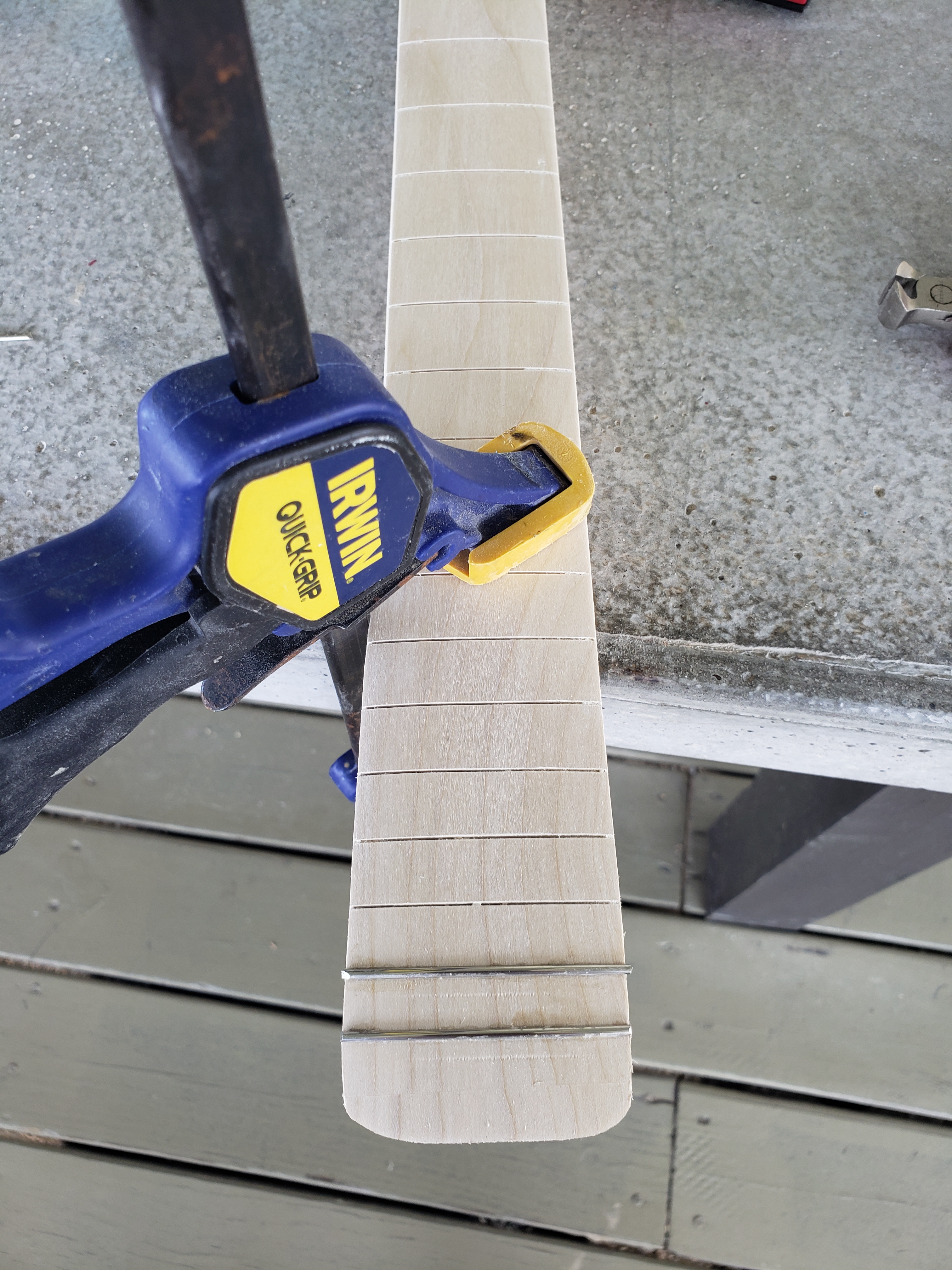
With the fretboard slotted, I used the same neck template to cut and rout the fretboard to match the neck, then glued the two pieces together, once again using way too many clamps.
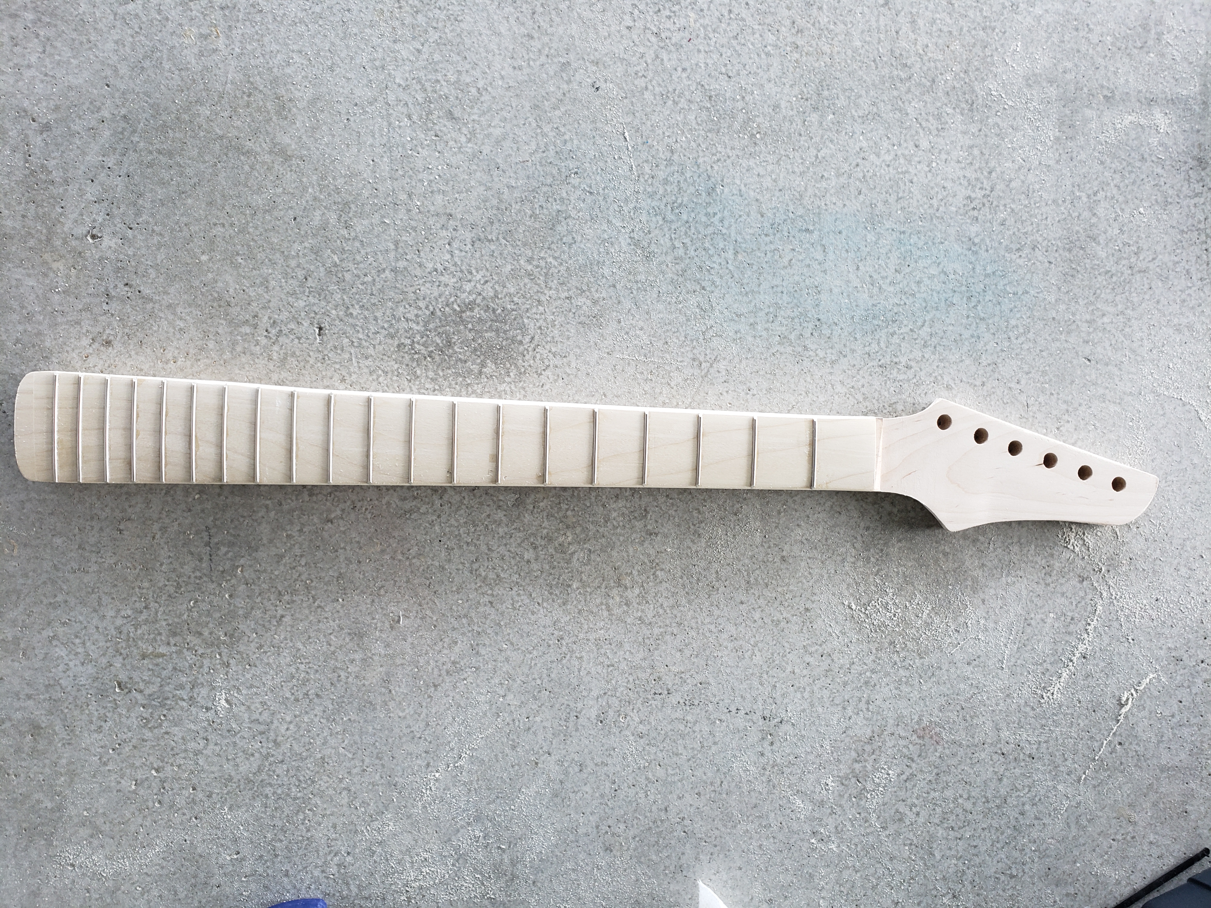
With the fretboard attached, I did a little more sanding and one more test fit.
To finish assembling the neck, I just needed to radius the fretboard and install the frets. To radius the fretboard, I 3D printed a sanding block with a 9.5″ radius and attached the sandpaper with doublesided tape. Eventually I’ll probably add some Velcro instead of the tape, but for now the tape worked.
Unfortunately I don’t have one of the fancy (and expensive) fretpresses, so I decided to make my own using a $5 clamp from menards and 3D printing the other pieces I need. I tried just using a hammer to install a couple of the frets, and it worked fine, but I definitely felt like I had more control with the clamp.
My process for inserting the frets was pretty simple; I would lay the fret wire on the slot and cut it, leaving a little overhang on both ends. I would then remove the wire, add some superglue to the slot, position the wire by hand, then use the clamp the press it into final position. I then had to repeat the process 20 more times. It was tedious, but it wasn’t awful. I then trimmed the ends of the wire and ran both sides of the neck across a belt sander to quickly remove any burrs. I still have to level and polish the frets and finish sand the rest of the neck, but for all practical purposes, the neck is ready to play, minus the nut. For this neck I’m using a bone nut and will install it last, when I’m ready to do the final guitar setup.
I know that I said in my last post that I was going to use one of the pre-built necks for this guitar, but then I remembered that this guitar is going to use nylon strings. The necks I bought already have truss rods installed, which is really a good thing, but truss rods are most beneficial for steel stringed guitars and not necessary for guitars with nylon strings so I decided to make a neck for this build. But before I started on the neck, I needed to cut the neck pocket in the body.
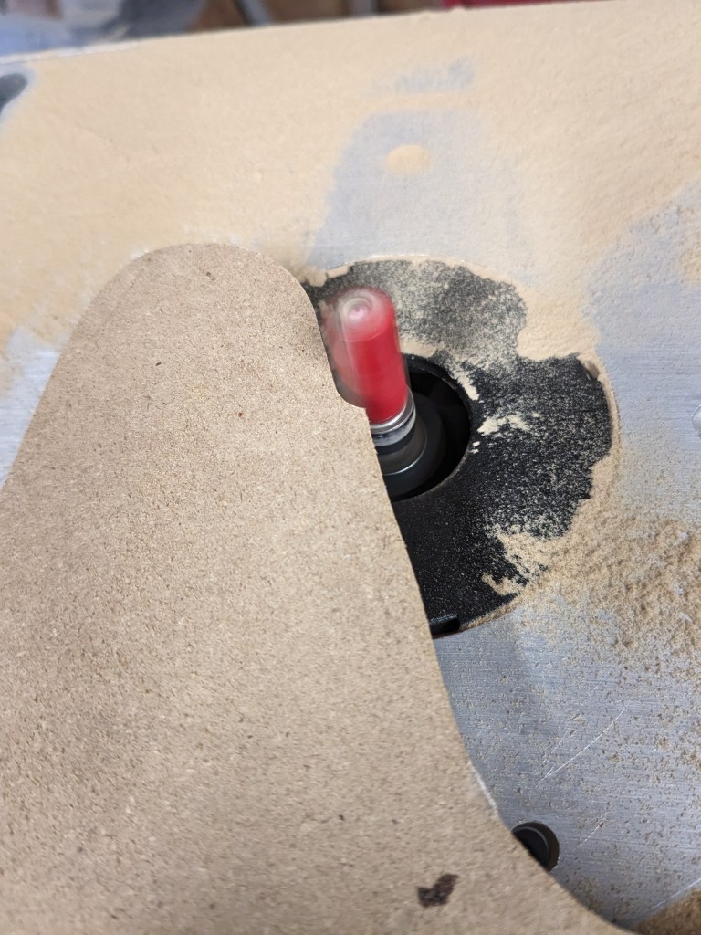
Because of the way I designed this guitar, I was able to use a scroll saw to cut out the neck pocket close to the lines, then attach the template I 3D printed to get the final shape.
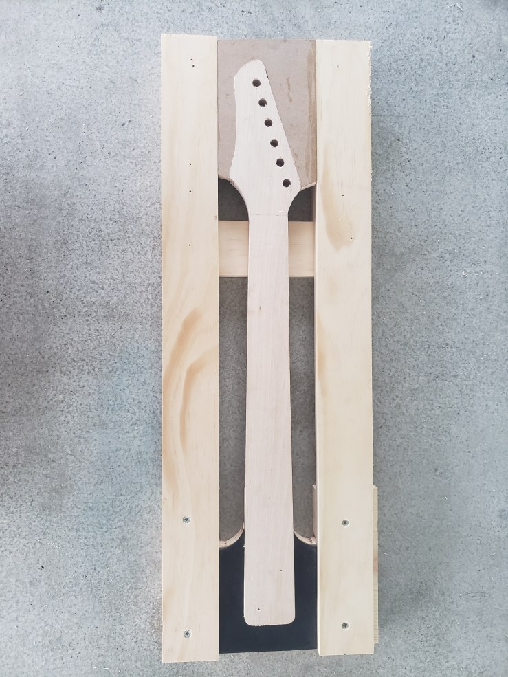
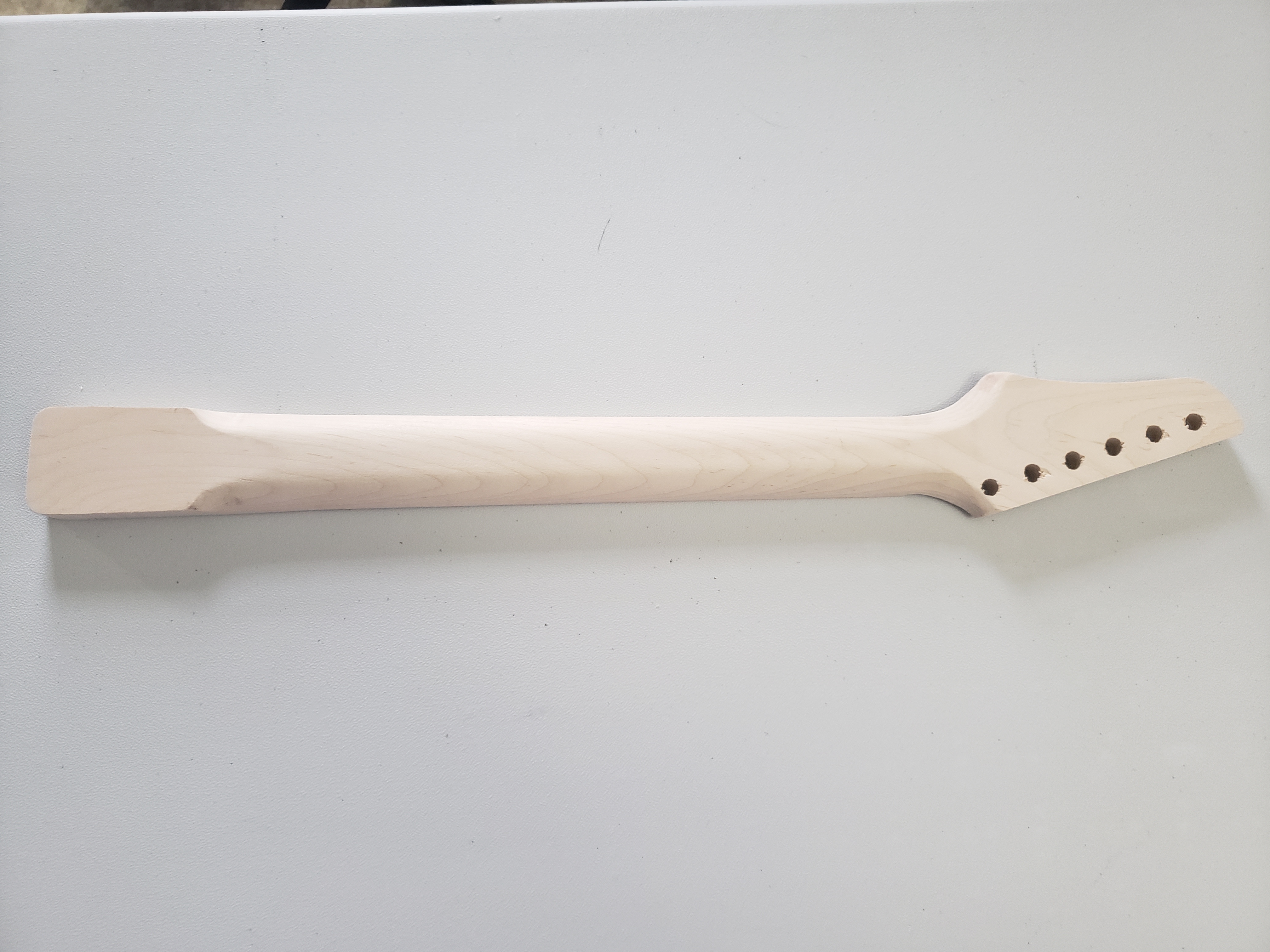
With the neck pocket routed, it was time to begin making the neck. I started the process by grabbing a piece of maple and marking a center line before aligning my template. Unfortunately I didn’t think to take a picture of the process this time, so here’s a few pictures of a neck I did out of poplar.
Like the body, I cut out the neck close to the template lines, then used the router with a pattern bit to get an exact match. I make several passes with the router, taking just a little off with each pass so I don’t risk tearing the wood. I then use a drill press to add the tuner holes based on the same template.
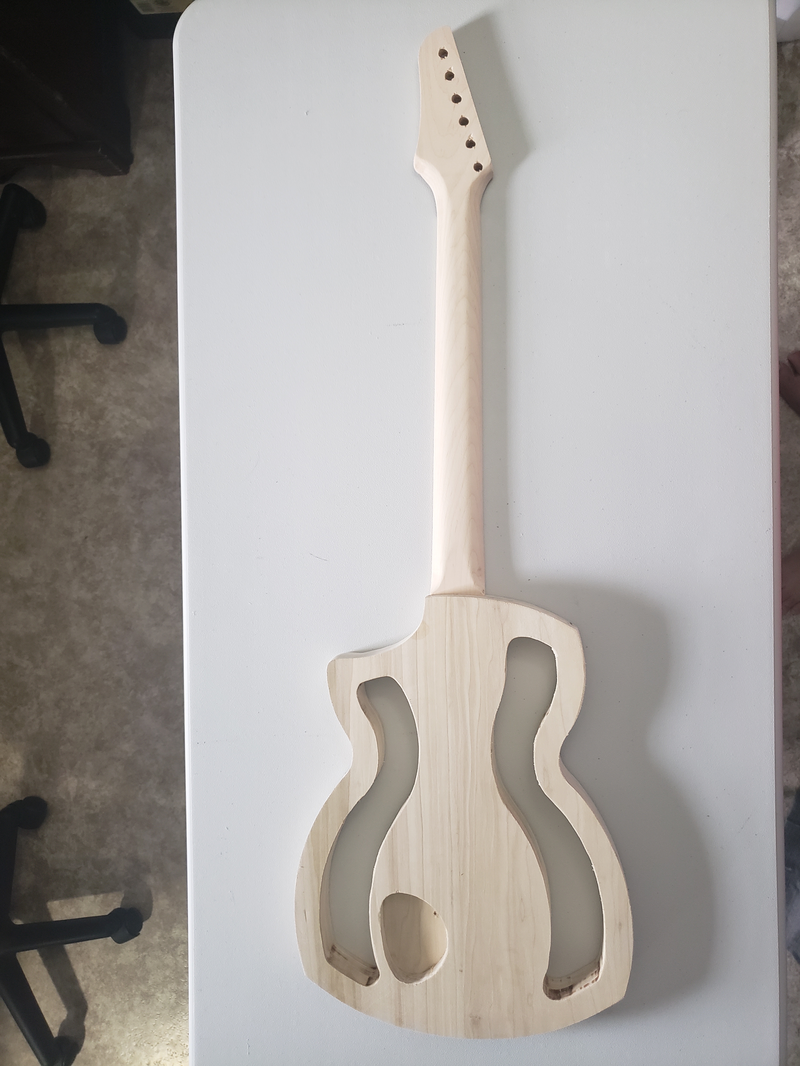
With the basic neck shape done, I proceeded to test fit the piece into the neck pocket on the body. The body was still in very rough shape, but the neck fit perfectly, so I was ready to continue shaping the neck.
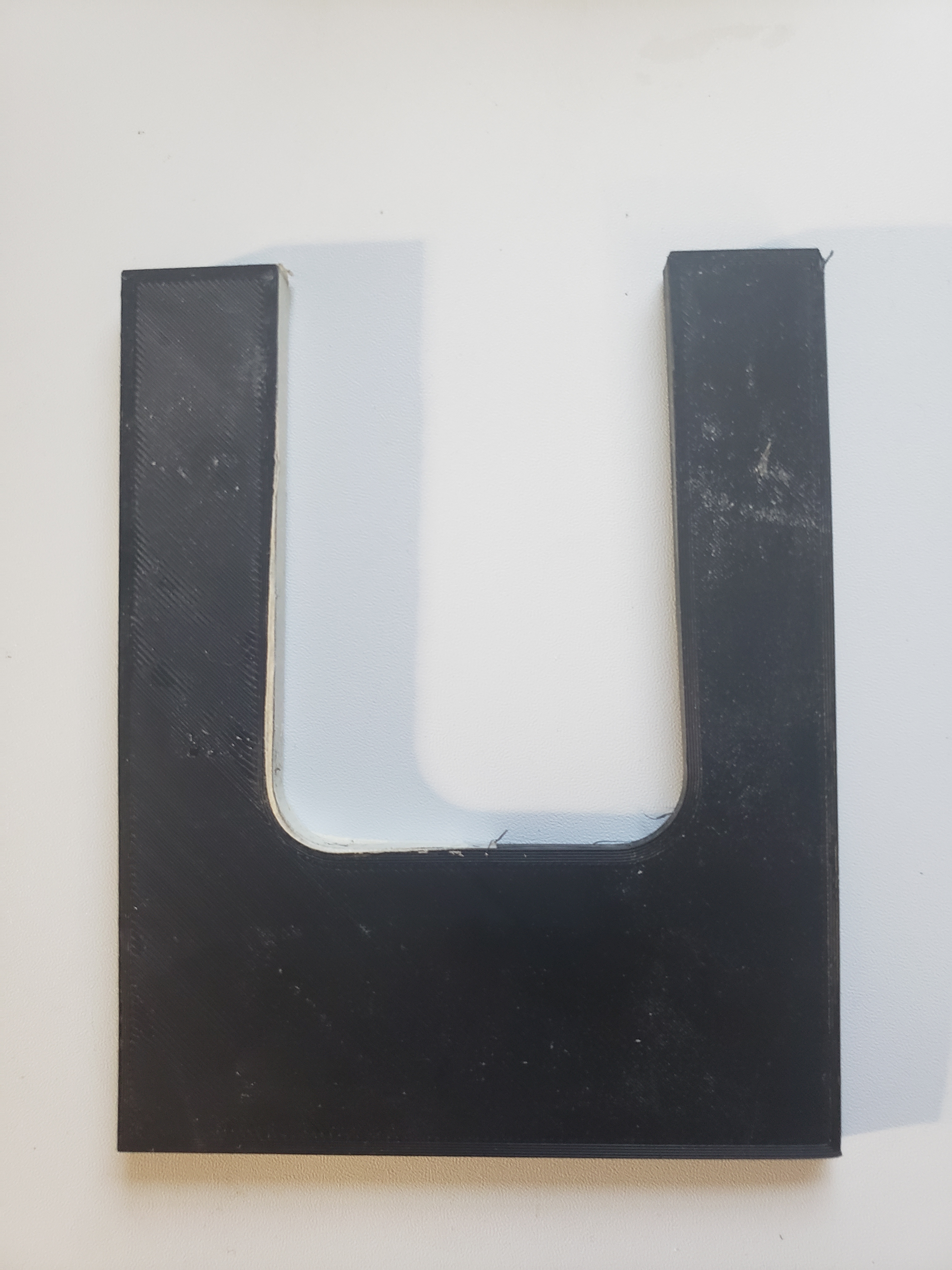
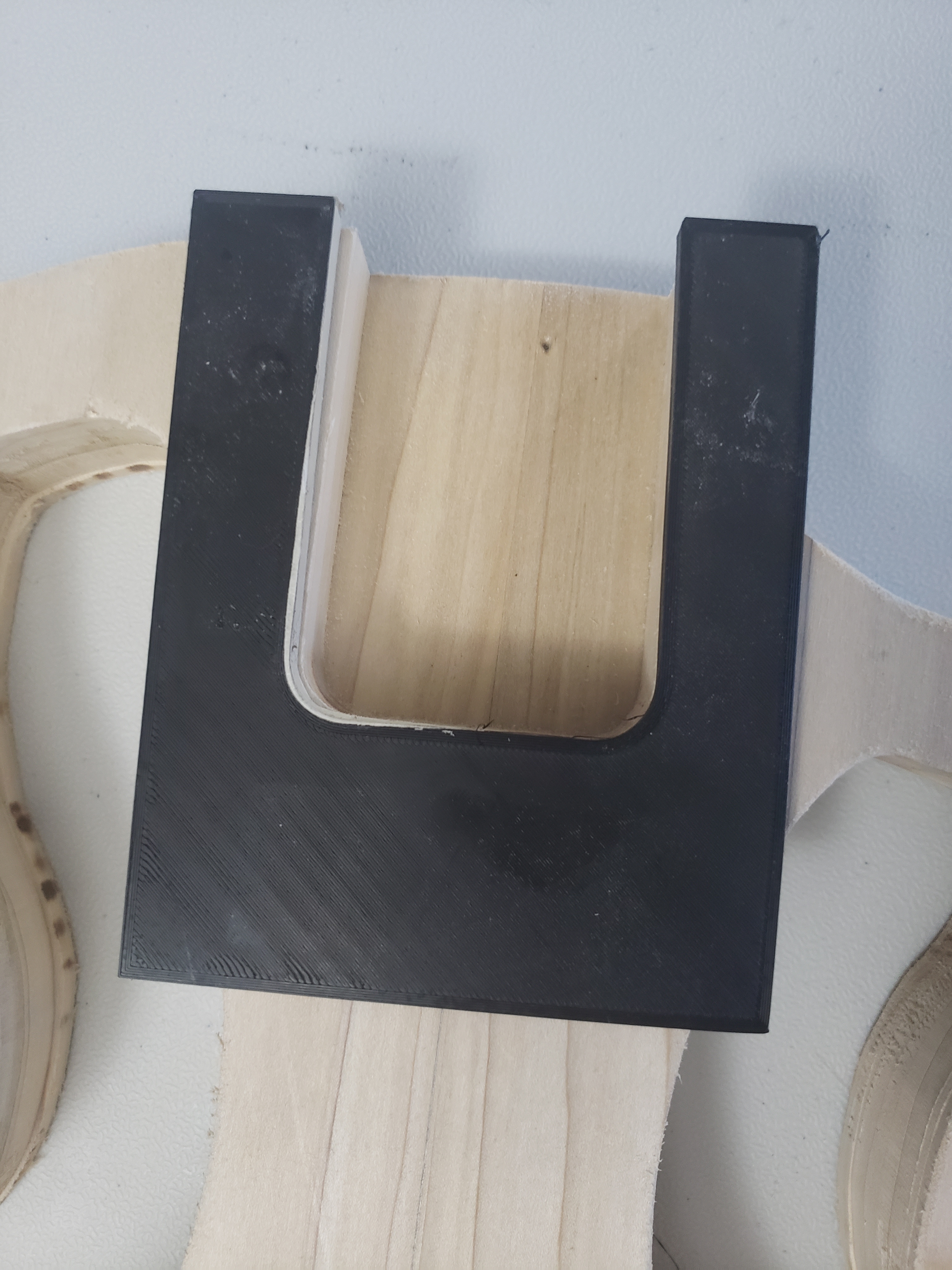
There are many different guitar neck designs, and even more ways to shape them, so of course I chose to ignore all of the conventional ways and design my own neck shaping jig.
This jig allows me to use either a rounded or 45 degree angle router bit to shape the rear sides of the neck depending on how aggressive I want the angle to be. For this one, I went with the 45 degree bit. Then, by just flipping the entire jig over, I was able to use a router with the pattern bit set to the proper depth to remove some stock from the head.
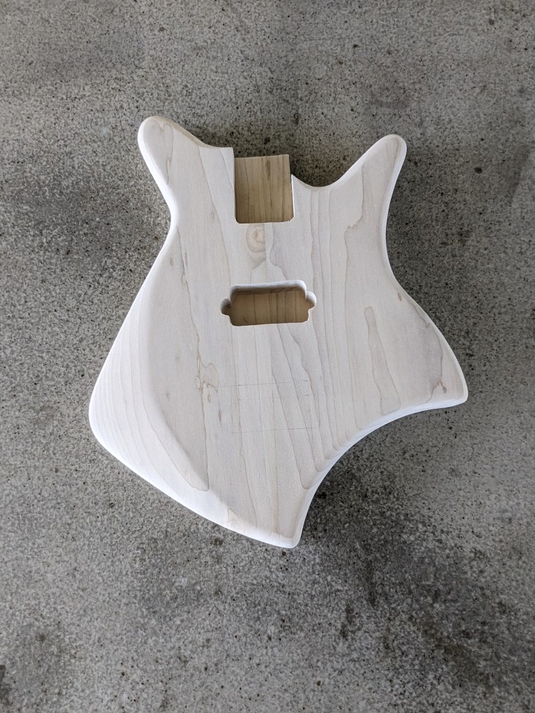
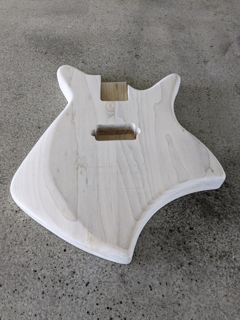
So with the neck ready to move on to sanding and assembly, I decided to cut the control cavity into the back of the guitar, then glue the front and back pieces together using every clamp I have.
Then, when the body had adequate time to cure, I did one more test fit before beginning the neck assembly and sanding.